缸体气缸孔镗削动力头的设计(含cad零件图和装配图)
来源:wenku168.com 资料编号:WK1687114 资料等级:★★★★★ %E8%B5%84%E6%96%99%E7%BC%96%E5%8F%B7%EF%BC%9AWK1687114
资料介绍
缸体气缸孔镗削动力头的设计(含cad零件图和装配图)(含选题审批表,任务书,开题报告,中期检查表,论文说明书11700字,CAD图纸8张)
摘 要:机床中,动力头是机床的核心部件,直接反应着机床的加工性能。而零件是否能达到加工要求,主要取决于机床本身动力头的设计与制造精度是否达到了一定的程度。本设计是镗床动力头,用于加工气缸孔。本设计主要是对动力头的动力学参数和运动学方案的确定,再根据动力头的传动方案,设计出主轴箱,即主轴箱、主轴、传动轴和齿轮的参数,选定主轴和传动轴的轴承并对其进行校核。而动力头的进给运动采用液压传动的方式,并进行液压系统的设计与计算,得到一个完整的液压传动系统方案。最终完一个镗床动力头的设计。
关键字:动力头;镗床;镗削加工;液压系统
The Design of Boring Machine Kinetic Head For Cylinder Hole
Abstract: In the machine tool, the boring head is the core component of the machine, which reflects the processing performance directly. And the design of boring head itself and whether the precision of manufacture achieves certain degree decide whether the parts can achieve processing requirements. This design is about boring head, which is used for machining cylinder hole. I firstly focused on how to determine the kinematics parameters and kinematical programs of the boring head. Then, on the basis of the power transmission project, I designed the spindle box, namely the spindle box, spindle, transmission shaft and the parameter selection, selected spindle and drive shaft bearings and do the checking. I used hydraulic transmission in feeding movement of power head,and designed and calculated the hydraulic system to get a full hydraulic transmission system. In this way, I finally accomplished the design of a boring head.
Keywords: power head Boring ; machine; Boring ; Hydraulic system
目 录
摘要 1
关键字 1
1 前言 1
2 动力学参数的选定 2
2.1 切削力计算 2
2.1 选择电动机 3
3 运动学及结构方案的确定 3
3.1 主运动传动方案的一般要求 3
3.2 主轴布置方案 3
3.3 主轴布置方案评价 4
4 主运动结构设计 5
4.1 传动装置传动比 5
4.2 计算传动装置的运动和动力参数 5
4.2.1 转速 5
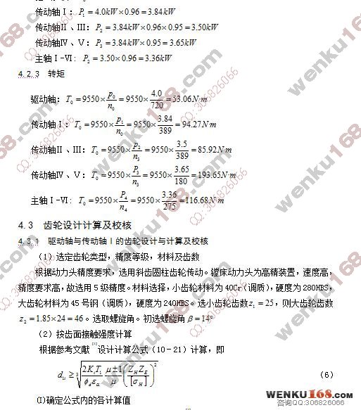
4.2.2 功率 6
4.2.3 转矩 6
4.3 齿轮设计计算及校核 6
4.3.1 驱动轴与传动轴Ⅰ的齿轮设计与计算及校核 6
4.3.2 主轴与传动轴Ⅰ的齿轮设计与计算及校核 11
4.3.3 传动轴Ⅰ与传动轴Ⅳ、Ⅴ的齿轮设计计算 15
4.4 传动轴Ⅰ的设计、校核 15
4.4.1 初步确定轴的最小直径 15
4.4.2 轴的结构设计 15
4.4.3 求轴上的载荷 16
4.4.4 按弯扭合成应力校核轴的强度 19
4.4.5 精确校核轴的疲劳强度 20
4.5 主轴的设计 22
4.6 键的选择及其校核 23
4.6.1 键的选择 23
4.6.2 键的校核 23
4.7 轴承 23
4.7.1 轴承的选择 23
4.7.2 轴承寿命的校核(以主轴为例) 23
5 进给运动液压系统 26
5.1 负载分析 26
5.2 负载图和速度图的绘制 27
5.3 液压缸主要参数的确定 27
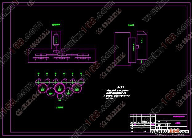
5.4 液压系统图的拟定 30
5.4.1 液压回路的选择 30
5.4.2 液压回路的综合 30
5.4.3 液压元件的选择 30
5.5 油液温升验算 34
6 结论 34
参考文献 35
致谢 36
附录 36
附录
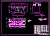
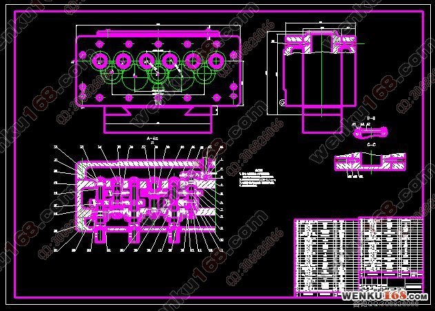
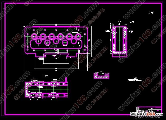
附录1:主轴箱体零件图
附录2:主轴零件图
附录3:传动轴Ⅰ零件图
附录4:斜齿轮零件图
附录5:液压系统图
附录6:控制原理图
附录7:主轴箱装配图
|